How osm2city Works
osm2city is a set of procedural programs, which together create plausible FlightGear scenery objects (buildings, roads, power lines, piers, platforms etc.) based on OpenStreetMap (OSM) data as well as data already existing in the default FlightGear World Scenery.
Plausible means here that the generated scenery should look in a way that a person not knowing the details of a specific location could believe that reality actually looks like that. Or that a person knowing the location would find a fair representation of landmarks and dimensions to find her / his way around in the virtual world.
This plausible world is achieved tried to be achieved by using heuristics to interpret the data input and combine it with a set of parameters as well as some randomness.
FlightGear and its World Scenery represent almost any location in our world. osm2city attempts to support this. Instead of a set of artists and programmers developing a specific scenery in a confined part of the world, which often means putting a considerable amount of hand-made objects into the scenery and tweaking stuff manually, osm2city uses generic heuristics, models, textures etc. and applies them to any part of the world with some parametrisation. This makes the task to cover the world a bit easier, but of course can only mimic the real world so much.
And then there are two twists to what is stated in the previous paragraph:
- The scenery generated by
osm2cityrespects the static objects put into the default scenery by diverse FlightGear scenery developers around the world — especially airports and landmarks like bridges, worship buildings etc. (see also the FlightGear Scenery Website and the Map over Scenery Models). I.e. the better the specific location is covered by manually created and placed static object, the closer to reality the combination withosm2citygenerated scenery objects might get. osm2citygenerated scenery is only as good as the underlying data. The higher the density and quality of the mapping done in OpenStreetMap, the better the scenery gets. In many parts of the world only a minor share of buildings is mapped at all. Often the only information available are floor plans and generic land-use zones — although the available map features in OSM are abundant and would allow for extreme sophistication (to be fair: this would then again require quite some sophistication inosm2cityto consume). In some cities (especially Europe) mappers are using Simple 3D Buildings, which results in nice representations inosm2city, which can come close to hand-crafted models.
Remember: FlightGears default scenery is only using freely available (world-wide) data and related freely available scenery objects. And so is osm2city. This data is often not as detailed as commercial products can provide.
Specific Stuff
Many features are explained in the parameters section. The subchapters below give some additional details.
Elevation and Detection of Water
osm2city generated scenery must play nicely with the default FlightGear scenery. This principle is also true if osm2city has access to better data in e.g. OSM.
Height above sea level is taken from the FlightGear scenery through some built in functionality in FlightGear (fgelev).
The FlightGear scenery is also used to determine, where there is water (the land-use information in FlightGear does sometimes deviate considerably from OSM — up to tens of meters). If PROBE_FOR_WATER is set to True, then buildings and roads are as far as possible not placed into water.
Land-use Handling
Land-use processing is a bit intricate, because OSM data is often insufficient or even lacking. Also for building heuristics it is necessary to have some idea about whether a built-up area is close to a centre and/or the type of settlement (e.g. village vs. town).
To understand the following it is important to first read chapter about Land-use parameters.
Once the land-use zone for built-up areas are read from OSM and/or generated (called “building_zones” in the code), lit areas are created by buffering all building zones and then merging as far as possible. These lit areas are not only used to determine, which streets should be lit, but are also used as a settlement clusters for cities and towns.
Only settlement areas tagged in OSM with place=city or place=town are considered for further processing of built-up areas, where apartments etc. exist. This is because the rural types are used as default, place=farm is treated specially and values for place like quarter, suburb, neighbourhood do not provide extra information. For city and town feature types Node, Way and Relation are read from OSM for key=place, however Way and Relation are reduced to a node by using the area’s centroid. Note that a pre-requisite for this to work is that the mapping in OSM has been done as instructed in Key Place.
In a first step all city or town places are linked to lit areas extended with specific water areas [1]. Then the zones are split into city_block objects, i.e. areas surrounded by streets — some of the polygons will be real city blocks, others will be border areas (the “city” part is not really true here - even a hamlet could in osm2city get divided into several city_blocks). The city blocks take over the land-use type (type can be non-osm if generated and therefore without real meaning).
Finally depending on the place type and the distance to the centroid a given city block has, it is assigned one of the following settlement types:
centre: the centre of a city (not available for towns). Max distance = population^(1/2)block: an area in the center of a city, where streets define blocks, and the buildings within the blocks most often are apartment like buildings, where the facades are aligned with the street and most often buildings are connected. Max distance = population^(5/8).dense: an area with dense population mostly living in apartments, but the apartment houses are not necessarily connected. Max distance = population^(2/3).periphery: an area with mostly (detached) houses. Outside of max distance fordense, but inside the boundaries of a settlement cluster for city/town (i.e. anything not centre/block or dense inside a settlement cluster is by default periphery).
There is also settlement type rural, which is the default for all those building zones, which re not within a lit area that is linked to a city or town place. In theory the main difference between periphery and rural is the ratio between a property’s lot size and the floor plan, where in rural regions the same family house size typically has more surrounding ground.
Please be aware that there is no “science” behind the chosen concentric ring radii and the settlement types. It is just a heuristic / an observation that the farther away from the city centre you get, the less dense the area. Also the settlement area is “some” function of the population (and the commuting workers into a city/town from outside are neglected). Also in some areas of the world densities are higher. This can be corrected with a linear parameter. The population is taken as is from OSM - if missing a parametrised default population is used.
The following table shows the resulting radii in metres for some example population sizes:
| Place | Population | Centre | Block | Dense |
|---|---|---|---|---|
| Town | 10 000 | n/a | 316 | 464 |
| Town | 50 000 | n/a | 864 | 1357 |
| City | 100 000 | 316 | 1334 | 2154 |
| City | 200 000 | 447 | 2056 | 3419 |
| City | 1 000 000 | 1000 | 5623 | 10000 |
I.e. all city blocks linked to building zones are tested against these circles and if intersecting/within, then the most “centric” one is linked to the city block. The building zone gets the maximum settlement type of all related city blocks.
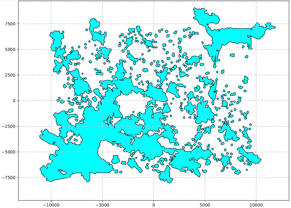
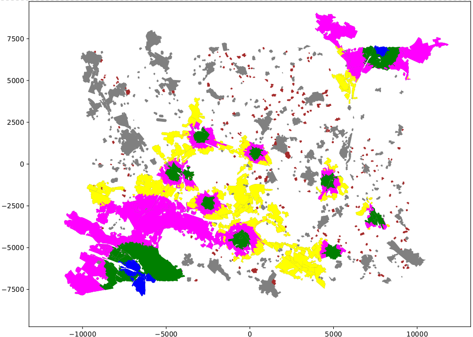
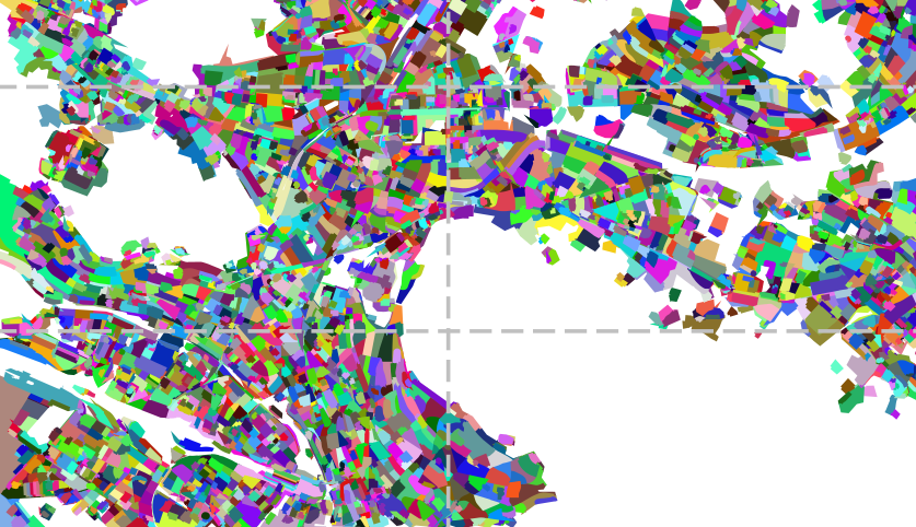
The following plots illustrate this around tile with 3088986 LSZH, where in most plots the city centre of Zurich is in the lower left corner and the smaller city of Winterthur is in the upper right corner.
Lit areas:
Settlement types (blue: centre, green: block, magenta: dense, yellow: periphery, grey: rural, brown: farmyard)
Pattern of city blocks:
| [1] | In cities like Copenhagen, Prague, Amsterdam, New York etc. larger water areas split the city. And that would make it look like the zones on the other side of the water area are not part of the city anymore. To make sure that this is still the case OSM data for water areas (river, canal, moat and riverbank) are added to the clustering to simulate continuous city areas. |
Generate Would-Be Buildings
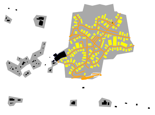
This is the core operation of the OWBB library. It generates buildings at probable places based on land-use zones, existing buildings and a set of parameters. At the core of the algorithm all streets within land-use zones are followed and to the left and right spots are searched for, where there would be place for an additional building — the building type being a function of the land-use zone, other buildings, street type and a set of parameters.
As an example the following picture shows generated buildings (yellow) based on land-use zones as defined in the previous chapter.
Roofs
The following are some pointers to how roofs work, and in particular code in roofs.py.
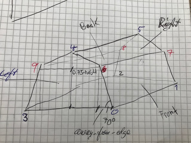
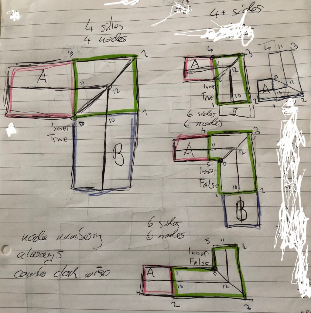
Gabled Around Edge
There are three situations, where a gabled roof around an edge is done. See also class RoofHints in roofs.py:
- A 4-sided building with 4 nodes and 2 adjacent buildings share 1 common node with the building (if there is only one neighbour building or if the 2 neighbours are on each side, then a gabled roof is done). If more than 2 neighbours we would not know what to do.
- A somewhat square-shaped building with 5 nodes and 5 sides, where the inner node is shared with a neighbour building. It is a requirement that the inner node is making an angle between 170 and 190 degrees with the previous/next node. Otherwise the roof just gets a skeleton roof.
- A L-shaped building with 6 nodes and 6 sides where the inner node is not shared with a neighbour building. If is a requirement that the inner node is making an angle between 80 and 100 degrees with the previous/next node. Otherwise the roof just gets a skeleton roof.
Aerodromes
Data for runways and helipads are depending on parameters read from the apt.dat file in $FG_ROOT/Airports/apt.dat.gz or directly from btg-files. This information is used to avoid having crossing OSM roads to be visible and potentially creating a considerable bump when a plane rolls over.
Data for airport boundaries are also read from the apt.dat file (not all airports have information about boundaries). This data is then merged with OSM data for aeroway=aerodrome (again not all airports might be modelled with a zone). The resulting land-use is making sure that buildings within these zones will look more like airport buildings: using flat roofs (unless the roof type is explicitly modelled in OSM) and using a modern facade texture. Also: no buildings are generated inside zones for aerodromes.